open menu
Data Networking

Fibre Optic Cables in Place of Electrical Cables for Data Networking – An Interface to the Future

Copper cable is becoming the bottleneck impeding fast data transmission over long distances. Fibre optic cables have been used here for years now and are coming ever closer to the printed circuit board and its electronics.

No matter how far we look back, data rates have always been increasing. One of the first ‘high-speed’ modems transmitted at 14.4 kilobits per second; today, internet connections are available with 200 Mbps. One man already roughly predicted this in 1965(!): Gordon Moore, co-founder of Intel, estimated that the density of integrated circuits would double every year. This statement went down in the industry’s history as ‘Moore’s Law’. Annually increasing circuit densities, one could reason, also meant increasing data rates.

These days, which some people call the post-Moore’s Law era, the drivers for rising data rates are megatrends such as 5G mobile communications, 4K video streaming and the cloud. This brings up the pressing question of how our networks will have to be designed in order to cope with these high data rates. One – perhaps the most relevant – answer could be the next generation of fibre optic technology, ‘coherent optics’.

The end of the electron is the beginning of the photon

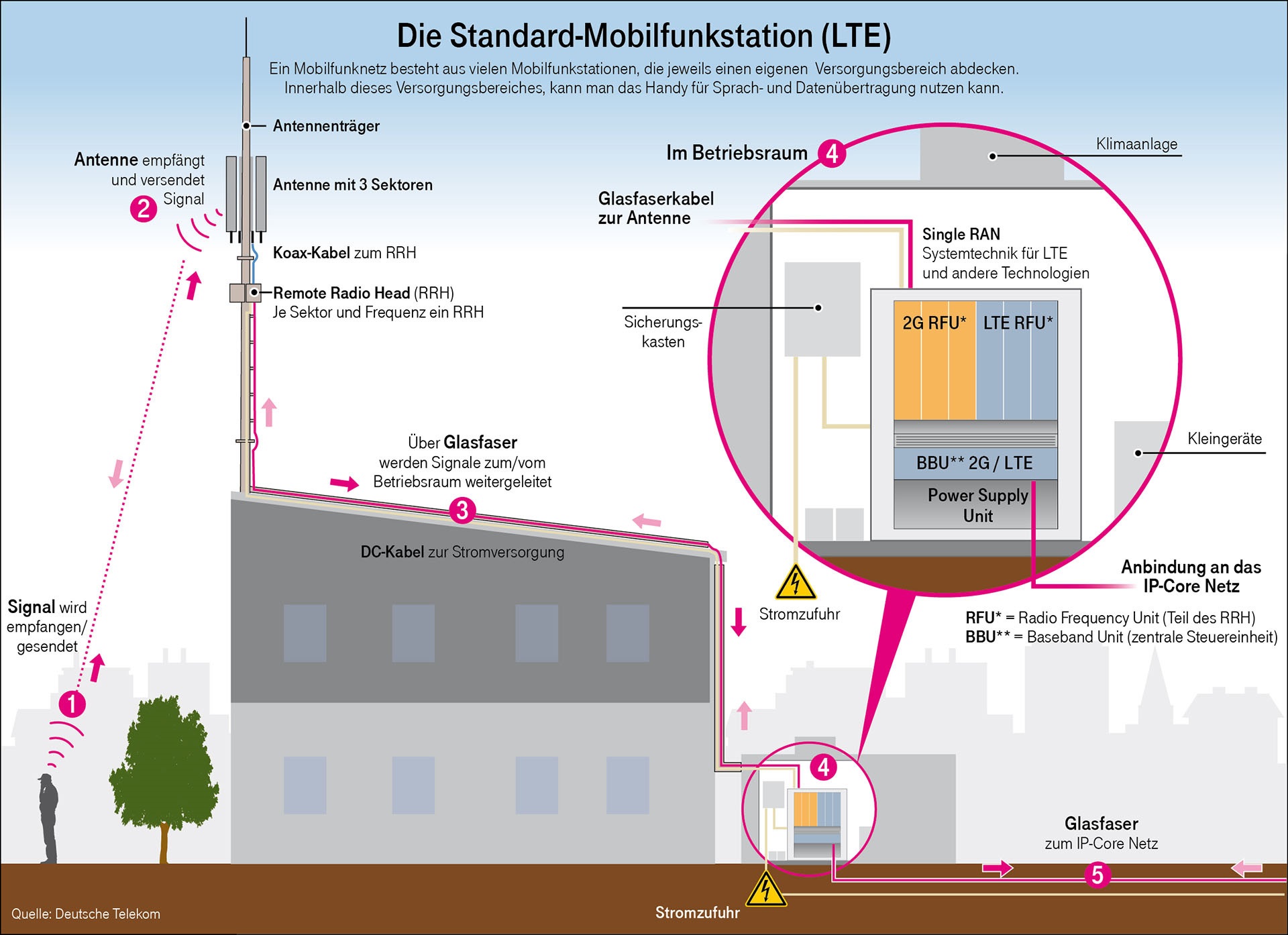
LTE Mobile station
Fig. 1: Fibre to the antenna (FTTA) (Source: Deutsche Telekom)

Copper lines put the brakes on fast data. Already today, data travels long distances by optical fibre. It seems the time has come for data to switch from copper to optical fibre for even ultra-short distances (a few centimetres) in order to flow faster. The fibre optic connection is thus coming closer to the user, or the integrated circuits. There are already so many names for it, including ‘fibre to the home (FTTH), ‘fibre to the cabinet’ (FTTC) and ‘fibre to the desk’ (FTTD), that the generic name FTTX has arisen. The ‘X’ stands for all possible fibre optic demarcation points. Particularly interesting demarcation points are fibre to the antenna in 5G/LTE networks (see Figure 1) and fibre to the chip in data centres.

In the mobile radio network, the optical fibre moves closer to the antenna and thus to the subscriber. In data centres, the fibre extends to the chip and thus skips the last few centimetres of copper wire on the printed circuit board.
Switching from copper to optical fibre alone will not even be remotely enough to cope with the massive amounts of data in the next few decades. New fibre optic technologies are hence indispensable. The key word here is ‘coherent optics’. The previous generation of optical transceivers only used the amplitude, i.e., light on, light off, for data transmission. 

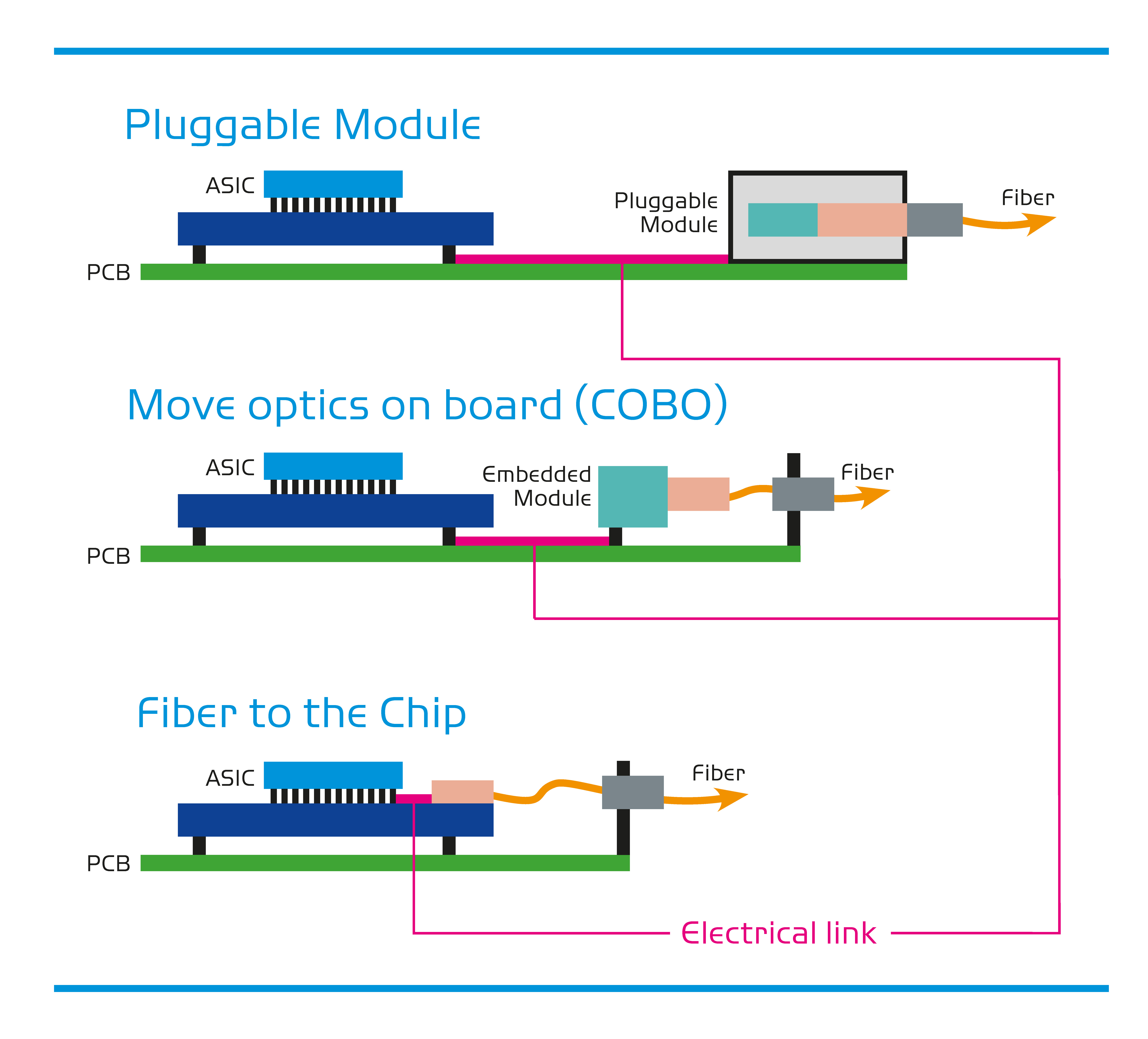
copper line
Fig. 2: Shortening of the copper line (magenta, ‘electrical link’)

This is comparable to Boy Scouts sending Morse code by torch at night. The new coherent optical transceivers also use (binary) polarisation, phase shift and various wavelengths. They multiply the data rate in this way.

Not only for coax cables on the antenna mast, but also on the printed circuit board, engineers are working hard to shorten the length of the electrical copper line. Why? Even short copper lines slow down the data rate. Instead of the optical transceiver module being placed on the faceplate (see Figure 2), the opto-electrical interface is moved closer to the circuit.

Examples from Yamaichi’s data networking portfolio

CFP2 ACO and DCO: ACO (analogue coherent optics) and DCO (digital coherent optics) are the new standards in fibre optic technology. Yamaichi supplies leading telecommunications equipment manufacturers with the corresponding connectors and sockets.

The ACO (4×56G) and DCO (4×64G) CFP2 connectors and sockets from Yamaichi feature improved insertion loss (IL) performance compared with the predecessor CFP2 (4×28G). Yamaichi is ahead of the MSA here. The old IL of –4.5 dB is significantly worse than the new –2.0 dB (both at 28 GHz). This yields the increase in data rate to 64 Gbps instead of 28 Gbps per cable pair. Example from practice: Through the design-in from Yamaichi, a customer was able to increase the reach of a wavelength division multiplexer (WDM) by 100 km.

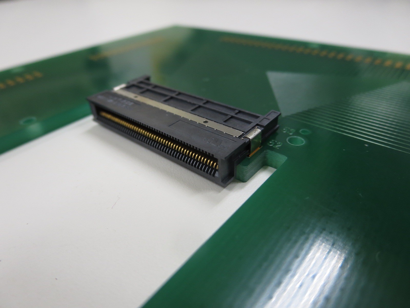
CFP2 MMC: If there is very little space on top, then ‘mid-mount’ is the solution. The connector and the cage in this case are not mounted on the PCB, but rather recessed in it (see Figure 3). This allows for higher heat sinks with unchanged housing dimensions and a very flat housing.

Host connector recessed in the PCB via mid-mount technology
Fig. 3: Host connector recessed in the PCB via mid-mount technology

Example from practice: A Yamaichi customer realised ultra-flat line cards of the next generation (coherent optics) with only ½ rack units thanks to mid-mount technology and, through this, is unparalleled on the market.

QSFP112G-PAM4: Yamaichi has the fastest QSFP (Style A) socket on the market, at 112 Gbps PAM4 per channel. That makes a 400G interface with only four channels, and this with backwards compatibility with the previous QSFP.

Electrical signal modulation is optimised

A copper line for fast data is like a path through a field for a racing bike. Even if you want to avoid it, sometimes there’s no way around it. So you have to get the most out of the copper side as well. Visitors to trade fairs such as ECOC or DesignCon frequently come across the term ‘112G-PAM4’. ‘112G’ stands for 112 Gbps per channel (one channel = one differential pair of copper wires). ‘PAM4’ stands for pulse-amplitude modulation with four levels. ‘PAM4’ doubles the data rate of the old modulation type NRZ. With NRZ a high level means ‘logic 1’ and a low level means ‘logic 0’. There are only two levels per unit time there. With PAM4 there are four levels.

An MSA defines the opto-electrical interface

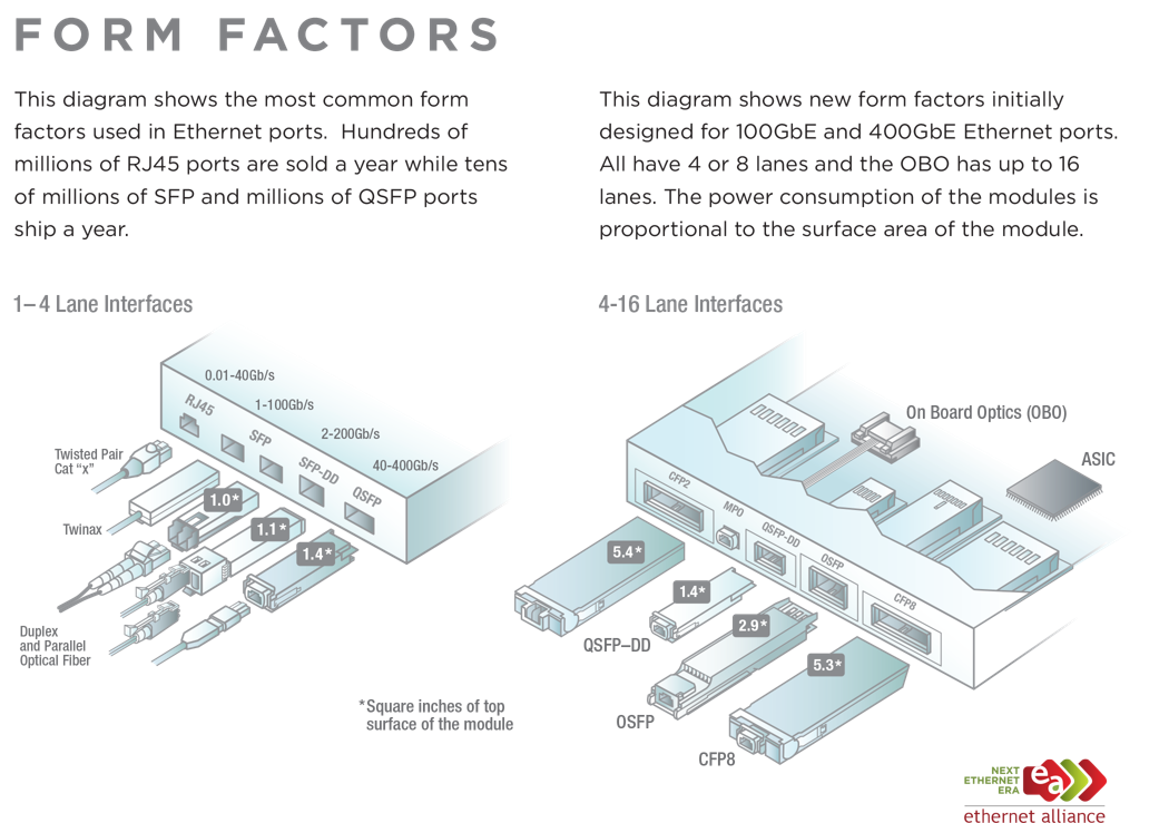
The standards for opto-electrical interfaces, also known as form factors, differ according to the application, transmission distance, number of channels and other factors. The Ethernet Alliance has compiled a list of the most common ones (see Figure 4). The most widespread is SFP (RJ45 is used even more frequently, but is purely electrical.) The newest form factor, which comes the closest to the circuit, is ‘OBO’. The multi-source agreements (MSA) are the ‘guardians of the grail’ for the various form factors. The interesting thing about an MSA is that market participants (including competitors) get together to technically define a standard and help it break into the market. The MSA gives potential buyers (i.e. customers) certainty regarding ‘fit, form and function’ and makes it easier to implement a multi-source strategy. Customers of a standard can divide their requirements between several manufacturers and even combine subcomponents (cage from manufacturer A, connector from manufacturer B etc.).

Form Facotrs
Fig. 4: Form factors (Source: Ethernet Alliance)

An MSA wants ‘its’ standard to be successful on the market. That is why, for once, competitors also work hand in hand here. A question naturally arises: how do people come to an agreement within an MSA? The following process has proven itself: Members submit their concepts and review one another’s. The best concept is selected as the guiding concept of the MSA. Yamaichi Electronics is one of the few chosen ones whose proposal for the guiding concept was selected for several MSAs (for plug and connector): for CFP2, CFP4, CFP8 and DSFP (see Figure 4).

Yamaichi supplies the electrical connectors and the mechanical components

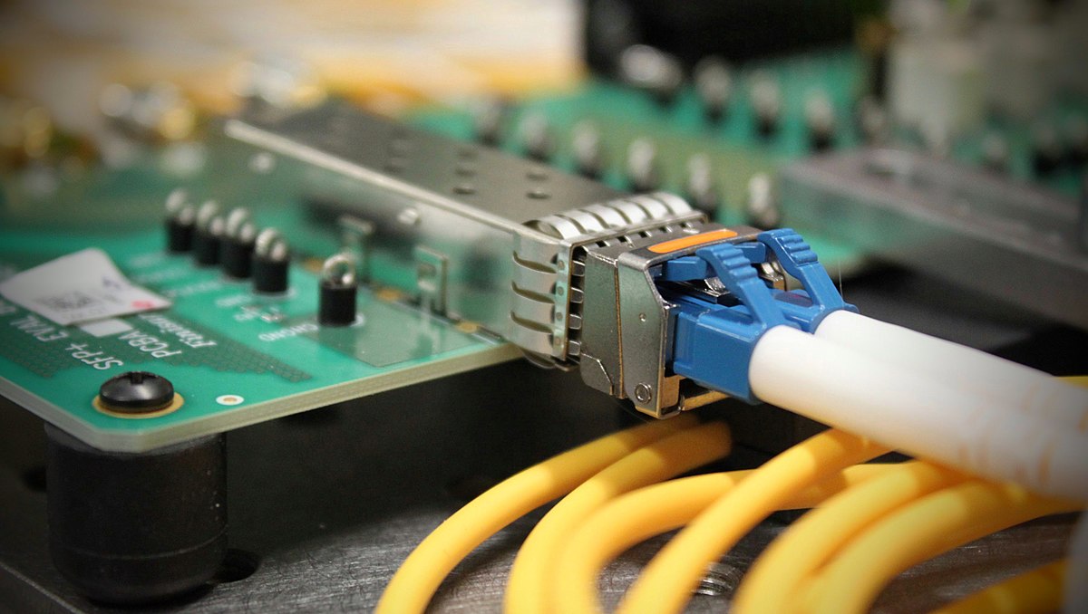
SFP-Transceiver
Fig. 5: SFP transceiver in an SFP cage – optical fibres at the front and printed circuit board at the back (Source: Christophe Finot, CC BY-SA 3.0)

Data travelling on the fibre optic data highway must switch to an electrical line for the last mile. An optical transceiver (see Figure 5) converts the light signal into an electrical signal. For the transition of the electrical signal from the transceiver to the printed circuit board, Yamaichi Electronics provides high-quality solutions for fast and error-free data transmission. For this, Yamaichi makes use of its technical lead, its close cooperation with the customer, e.g. in the event of necessary deviations from the standard product, and the high signal quality it achieves with its products.

Author: David Binder
Business Development Manager Data Networking